# Assembly guide
> Before assembling the duck, you should first [configure your motors](./configure_motors.md)
## Requirements :
You will need :
- A soldering iron, and basic electronics tools and skills
- X m3 screws (TODO : add the exact number)
- Some wire
- Loctite Threadlocker blue 243
> General note : Everytime you screw something in the motors metal against metal, you want to use a little loctite threadlocker. This will prevent the screws from coming loose due to the vibrations during the operation of the robot. It adds a little time to to the build, but you'll be glad you took the time ;)
>
> Don't use loctite with the plastic screws
> At any time, you can refer to the CAD here : https://cad.onshape.com/documents/64074dfcfa379b37d8a47762/w/3650ab4221e215a4f65eb7fe/e/0505c262d882183a25049d05
## Steps :
### Assemble the trunk
Place the bearings in `trunk_bottom` like so, and insert M3 inserts in these holes. It's also a good time to insert the 4 M3 inserts in the bottom of this part to mount body parts later on.
 Then assamble `trunk_bottom` and `trunk_top`, and screw them together with 2 `M3x10` screws through these holes
 Mount the middle motor like so and screw it with the plastic screws that came with the motors :
 Insert `roll_motor_bottom` like this
 ### Assemble the feet
Both feet are the same.
First, assemble `foot_bottom_tpu` with `foot_bottom_pla`. Insert M3 inserts in these holes :
### Assemble the feet
Both feet are the same.
First, assemble `foot_bottom_tpu` with `foot_bottom_pla`. Insert M3 inserts in these holes :
 And screw the two parts together with two `M3x6` screws.
Then, insert M3 inserts in these holes in `foot_top` here :
And screw the two parts together with two `M3x6` screws.
Then, insert M3 inserts in these holes in `foot_top` here :
 And assemble everything like so. Make sure the driver side of the motor is on the `foot_top` part side :
You can add the foot switches like this too :
> You press fit them so that the switch is activated when the foot touches the ground
### Assemble the shins
Insert M3 Inserts in these holes of `leg_spacer` (on both sides. Insert 4 M3 inserts in total) :
And assemble everything like so. Make sure the driver side of the motor is on the `foot_top` part side :
You can add the foot switches like this too :
> You press fit them so that the switch is activated when the foot touches the ground
### Assemble the shins
Insert M3 Inserts in these holes of `leg_spacer` (on both sides. Insert 4 M3 inserts in total) :
 Then, first plug the motor cable in the foot's motor, and make it go through the `right_sheet` like so
 Then assemble like below:
 ### Assemble the thighs
The thigh is pretty much the same thing, except the `hip_pitch` motor is mounted this way (important for the zero position)
### Assemble the thighs
The thigh is pretty much the same thing, except the `hip_pitch` motor is mounted this way (important for the zero position)
 ### Assemble the hips
Mount `left_roll_to_pitch` or `right_roll_to_pitch`, here the parts are symmetrical so you have to use the right one.
### Assemble the hips
Mount `left_roll_to_pitch` or `right_roll_to_pitch`, here the parts are symmetrical so you have to use the right one.
 Mount `roll_motor_top` to the `hip_yaw` servo (screw from the bottom). Don't mount the servo to the trunk yet.
 Then mount `hip_roll` like this
 And insert the sub assembly like this
 Screw everything you can (with the plastic screws provided with the servos)
You can now mount the leg like this :
Screw everything you can (with the plastic screws provided with the servos)
You can now mount the leg like this :
 And do the same for the other leg :)
Your duck should now look like this
And do the same for the other leg :)
Your duck should now look like this
 ### Assemble the neck
You know the drill
### Assemble the neck
You know the drill
 ### Assemble the head mechanism
First, mount `head_pitch_to_yaw` like this
### Assemble the head mechanism
First, mount `head_pitch_to_yaw` like this
 Then, independently mount `head_yaw_to_roll` and `head_roll_mount` to `head_roll dof`
 (You can insert `head_bot_plate` and `body_middle_top` now too to avoid having to disassamble the head later)
Then
(You can insert `head_bot_plate` and `body_middle_top` now too to avoid having to disassamble the head later)
Then
 Then
Then
 Your duck should now look like this
 ### Mount the servo driver board
TODO take a photo
### Mount the IMU
Like this
> It's actually better to mount the IMU with the correct natural orientation, which would be flipped along the X axis compared to the pictures below
> In the picture below, the IMU is mounted upside down.
> It probably doesn't really matter a lot if you mount it upside down or not. You can configure how you mounted it later
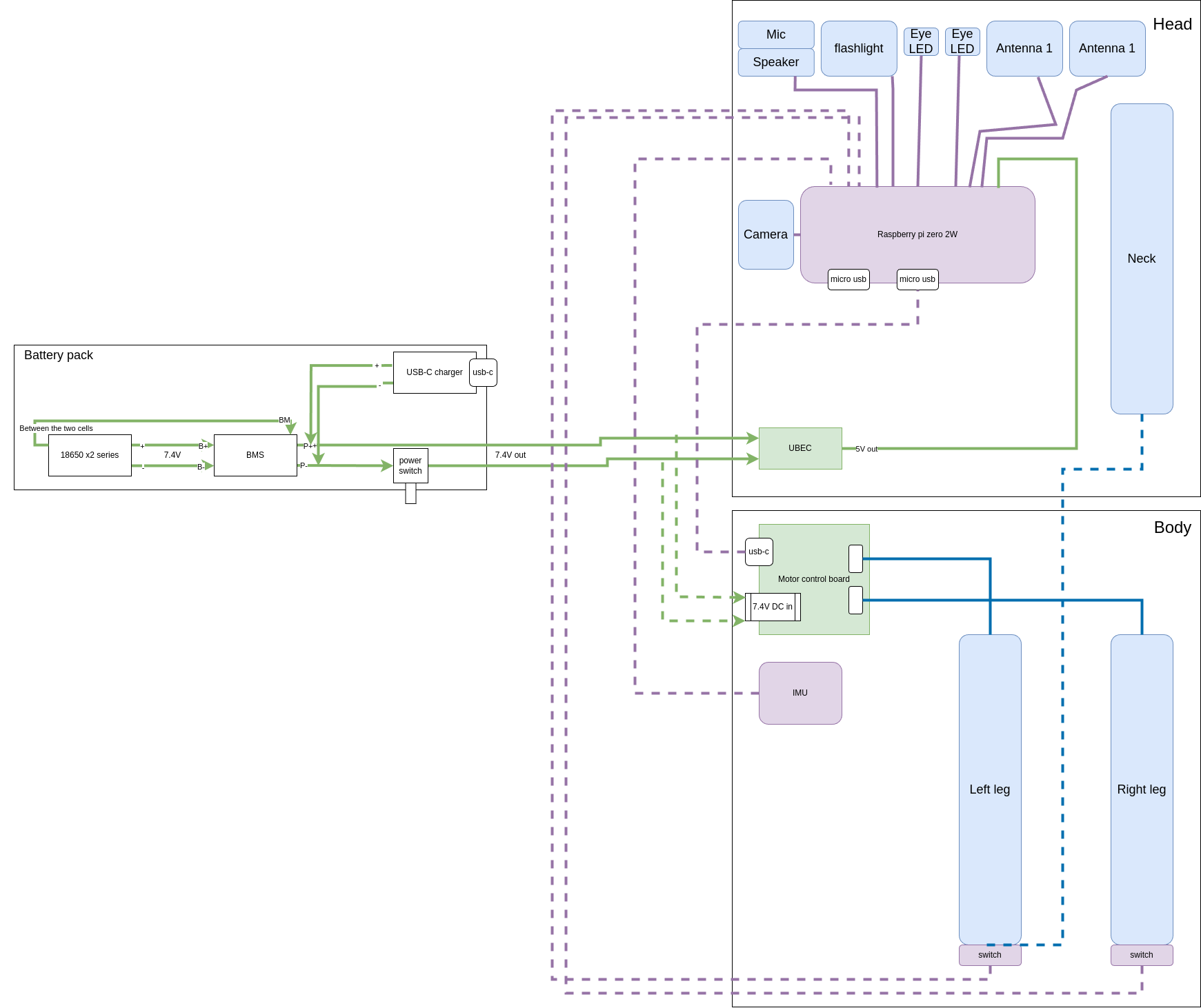
## Electronics
Here is the global electonics schematic for reference
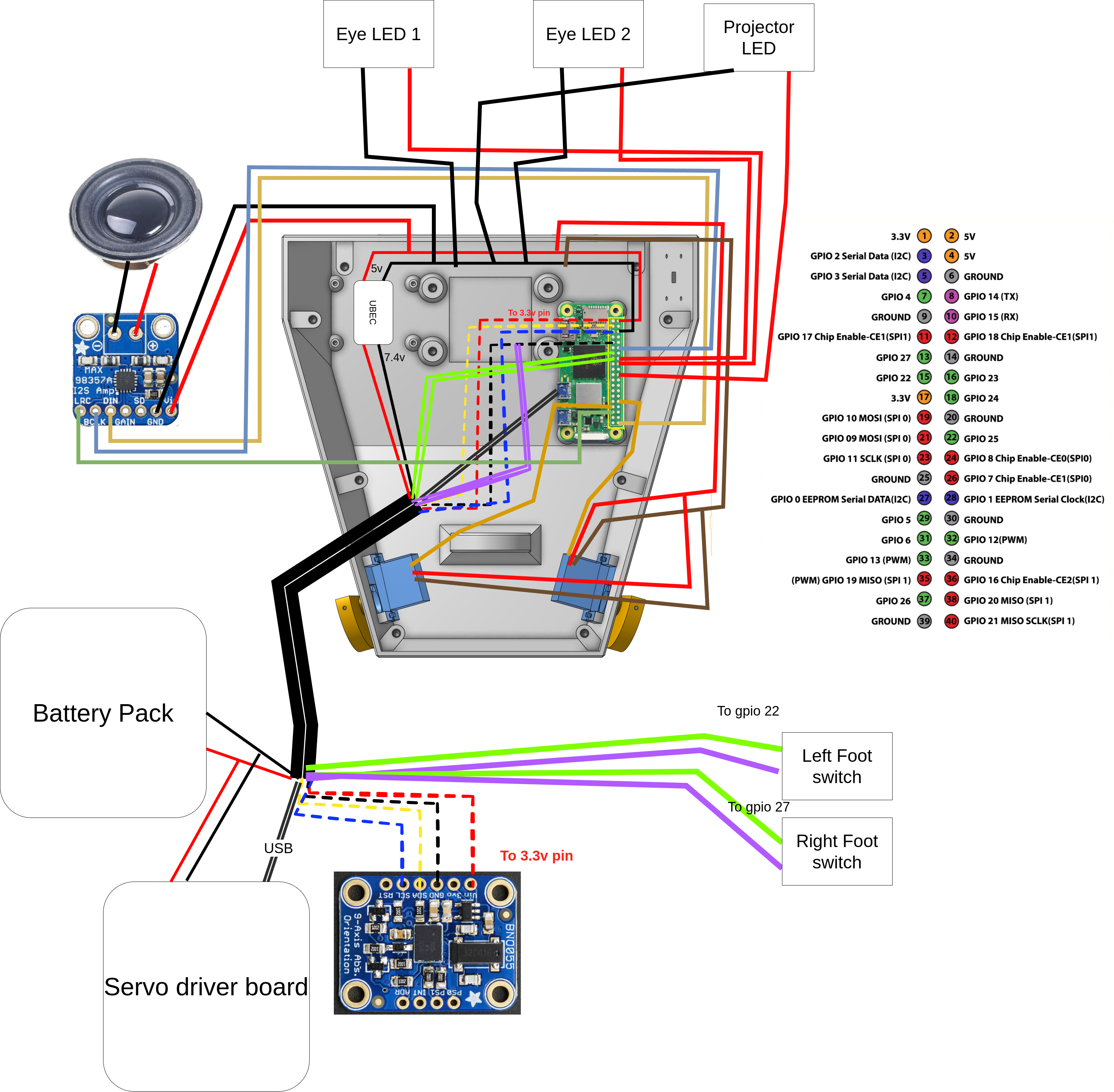
Here is how to wire the feet

### Battery pack
> To be safe, make sure your cells are charged to the same voltage before placing them in the holder.
### Head
First, insert the M3 inserts in all these holes

> TODO add instructions for expression features (camera, antennas, eye leds, projector and speaker)
Then insert the bearing, mount the ear motors and the raspberry pi zero 2w.
For reference, the inside of the head looks like this now

Then assemble the neck with the head like this

## Body
First screw on `body_middle_bottom`

Then insert the M3 inserts in all the holes of `body_middle_bottom` and `body_middle_top` on which we'll mount the battery pack and `body_front`.
Then mount `body_middle_top`, `body_front` and the battery pack
Et voila :)
> Now that your duck is fully assembled, you setup the raspberry pi and the runtime software [here](https://github.com/apirrone/Open_Duck_Mini_Runtime)
### Mount the servo driver board
TODO take a photo
### Mount the IMU
Like this
> It's actually better to mount the IMU with the correct natural orientation, which would be flipped along the X axis compared to the pictures below
> In the picture below, the IMU is mounted upside down.
> It probably doesn't really matter a lot if you mount it upside down or not. You can configure how you mounted it later
## Electronics
Here is the global electonics schematic for reference
Here is how to wire the feet

### Battery pack
> To be safe, make sure your cells are charged to the same voltage before placing them in the holder.
### Head
First, insert the M3 inserts in all these holes

> TODO add instructions for expression features (camera, antennas, eye leds, projector and speaker)
Then insert the bearing, mount the ear motors and the raspberry pi zero 2w.
For reference, the inside of the head looks like this now

Then assemble the neck with the head like this

## Body
First screw on `body_middle_bottom`

Then insert the M3 inserts in all the holes of `body_middle_bottom` and `body_middle_top` on which we'll mount the battery pack and `body_front`.
Then mount `body_middle_top`, `body_front` and the battery pack
Et voila :)
> Now that your duck is fully assembled, you setup the raspberry pi and the runtime software [here](https://github.com/apirrone/Open_Duck_Mini_Runtime)